Crystal parallel and series resonance


There are two modes in which a crystal oscillator can operate and these can be seen from the equivalent circuit diagram.
Ø Series resonance: This is a standard series resonance condition formed by the series connection of a capacitor and inductor. At the resonant frequency, fs, the capacitive and inductive reactances cancel and the impedance falls to a minimum equal to the resistance in the circuit, i.e. R.
fs=12πL C1−−−−√fs=12πL C1
It is found that in this mode the external circuit has very little effect on the crystal resonance.
Ø Parallel resonance: The parallel resonance for the quartz crystal condition is formed by a capacitor and inductor in parallel. At resonance the impedance of this circuit rises to a maximum. The actual resonant frequency, fp, derivation for this mode incorporates the inductance along with both capacitors seen in the equivalent circuit.
fs=12πL Co C1Co+C1−−−−−−−√fs=12πL Co C1Co+C1
When operating in this mode it will be seen that any capacitance introduced by the external circuit will also have an effect. As a result this 'load' capacitance forms part of the specification for the operation of the crystal - load values of 30pF, 20pF, etc are seen in the specifications. The calculations in the design of the oscillator should enable the correct load capacitance to be provided to the crystal. Changing the load capacitance can also be used to trim the exact frequency of the crystal to ensure that it is on exactly the correct frequency. Typically a small variable trimmer capacitor may be added to ensure that the correct load capacitance is provided.
This mode is sometimes referred to as the crystal's anti-resonant frequency. The reason for this is that the impedance of the circuit reaches a peak at resonance.
Quartz crystal resonators can operate in either mode, and in fact the difference between the parallel and series resonant frequencies is quite small. Typically they are only about 1% apart.
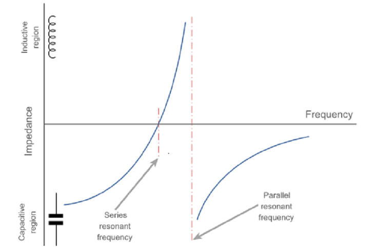
(Quartz crystal resonator impedance characteristic)
Of the two modes, the parallel mode is more commonly used, but either may be used. Oscillator circuits for using the different modes are naturally different, as one oscillates when the crystal reaches its maximum impedance whilst the other operates when the crystal reaches its minimum impedance.